T568A and T568B are the two color codes used in wiring RJ45 eight-position modular plugs. The American National Standard Institute/Telephone Industry Association/Electronics Industry Association (ANSI/TIA/EIA) wiring standards allow both of these color codes. The only difference is that the orange and green pairs are interchanged.
Because it provides backward compatibility for both one pair and two pair Universal Service Order codes (AT&T) USOC wiring schemes, the T568A wiring pattern is recognized as the preferred wiring pattern for this standard.
However, the T568B standard (used by VPI) is the most widely used wiring scheme, as it matches the older ATA&T 258A color code. It is also permitted by the ANSI/TIA/EIA standard, but it provides only a single pair backward compatibility to the USOC wiring scheme.
U.S. Government regulations require the use of the preferred T568A standard for wiring done under federal contracts.
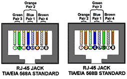
The following diagrams look at the jacks from the front. The wiring at the rear of the jack varies by manufacturer; it may not be the same sequence as the front. Compliance with the color codes is maintained by routing the connections at the back to the proper sequence at the front of the jack. This is done by a small printed-circuit board in the jack assembly. Cat 5e jacks (diagram below right) may have a twist inside the jack to reduce crosstalk.
COLOR-CODE STANDARDS
Last updated: 8/9/2004
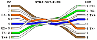
Again, please bear with me... Let's start with simple pin-out diagrams of the two types of UTP Ethernet cables and watch how committees can make a can of worms out of them. Here are the diagrams:
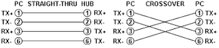
Note that the TX (transmitter) pins are connected to corresponding RX (receiver) pins, plus to plus and minus to minus. And that you must use a crossover cable to connect units with identical interfaces. If you use a straight-through cable, one of the two units must, in effect, perform the cross-over function.
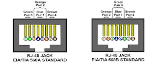
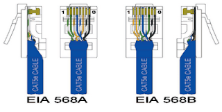
Two wire color-code standards apply: EIA/TIA 568A and EIA/TIA 568B. The codes are commonly depicted with RJ-45 jacks as follows (the view is from the front of the jacks):
If we apply the 568A color code and show all eight wires, our pin-out looks like this:
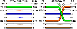
Note that pins 4, 5, 7, and 8 and the blue and brown pairs are not used in either standard. Quite contrary to what you may read elsewhere, these pins and wires are not used or required to implement 100BASE-TX duplexing--they are just plain wasted.
However, the actual cables are not physically that simple. In the diagrams, the orange pair of wires are not adjacent. The blue pair is upside-down. The right ends match RJ-45 jacks and the left ends do not. If, for example, we invert the left side of the 568A "straight"-thru cable to match a 568A jack--put one 180° twist in the entire cable from end-to-end--and twist together and rearrange the appropriate pairs, we get the following can-of-worms:
This further emphasizes, I hope, the importance of the word "twist" in making network cables which will work. You cannot use an flat-untwisted telephone cable for a network cable. Furthermore, you must use a pair of twisted wires to connect a set of transmitter pins to their corresponding receiver pins. You cannot use a wire from one pair and another wire from a different pair.
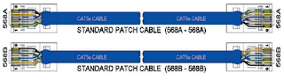
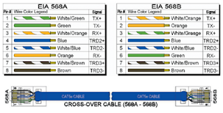
Keeping the above principles in mind, we can simplify the diagram for a 568A straight-thru cable by untwisting the wires, except the 180° twist in the entire cable, and bending the ends upward. Likewise, if we exchange the green and orange pairs in the 568A diagram we will get a simplified diagram for a 568B straight-thru cable. If we cross the green and orange pairs in the 568A diagram we will arrive at a simplified diagram for a crossover cable. All three are shown below.
This cabling guide highlights the differences between these wiring standards. It also provides insight for the steps involved in creating standard and crossover cables.
The 568A and 568B standards were developed to provide more effective communications for longer distances in a Cat5e cable segment than using non standard schemes. Fibre Optic cable is the only medium that is completely immune to crosstalk and EMI since it uses light to transfer data instead of electrical current.
The 568A and 568B colour code schemes are used to wire the RJ45 eight position modular plugs correctly. Both colour codes are approved by the American National Standard Institute/Telephone Industry Association/Electronics Industry Association (ANSI/TIA/EIA) wiring standards. There is no difference between the two wiring schemes in connectivity or performance when connected form one device to another, so long as the devices are wired for the same scheme. The only time when one scheme has an advantage over the other is when one end of a segment is connected to a modular device, and the other end to a punch block. In this case, the 568A scheme has the advantage of having a more natural progression of pairs at the punch block side.
Cables are generally made up of eight wires twisted together in four pairs. Each pair is easily identified by one of four primary colours and is intended to carry a signal and its return. The 568A wiring pattern is recognised as the preferred wiring scheme for standard use because it provides backward compatibility for both one pair and two pair Universal Service Order codes (AT&T) USOC wiring. U.S. Government regulations require the use of the preferred 568A standard for wiring installed under federal contracts.
However, N-Tron adopted the 568B standard since it is the most widely used in the industry today. It matches the older AT&T 258A colour code. It is also approved by the ANSI/TIA/EIA standard. This scheme provides one pair for backward compatibility to the USOC wiring scheme. This illustration will assist in identifying the differences between the 568A and 568B colour schemes. The difference between the two is that the orange and green pairs are interchanged as shown.
These standards specify a maximum segment length of 100 metres between two devices. This length includes patch panels and cables. When longer distances are desired, the use of switches, repeaters, or fibre optic media may be required.
A cable can be wired with correct continuity, but not necessarily with correct pairing. This often happens when the cable is terminated consistently at both ends, but in the wrong order. A dynamic or AC test is required to detect this type of error. If the only error is a split pair error, the cable will possess correct continuity but will likely cause crosstalk.
Crosstalk is the bleeding of signals carried by one pair of conductors, onto another pair through electrical induction. The conductors do not need to make contact with each other as the crosstalk is transferred magnetically. This is an unwanted effect that can cause slow transfer or completely inhibit the transfer of data signals over a long cable segment. The purpose of the wire twists found in Cat5e cable is to significantly reduce the crosstalk and its side effects.
Similarly, Electro Magnetic Interference (EMI) is an unwanted signal that is induced into the cable. The difference is that EMI is typically induced from a source that is external to the cable. This could be an electrical power cable or device, or in some cases adjacent Cat5e cables that do not adhere to the 568A and 568B standards.
Attenuation is the loss of signal in a cable segment due to the resistance of the wire plus other electrical factors that cause additional resistance. Longer cable length, poor connections, bad insulation, high levels of crosstalk, and EMI will all increase the total level of attenuation.
Creating Cat5e crossover cables
Two Ethernet switches may be connected together with a standard patch cable as long as both devices are compliant with the MDIX standard. Basically, the MDIX standard automatically performs the crossover functions without user configuration. It allows the switch to properly align the conductors internally. In some situations, connection of similar devices such as legacy hubs or Network Interface Cards may be accomplished by the use of a crossover cable. Therefore, the cable itself will physically perform the crossover function. A crossover cable can be easily created by using the 568A scheme at one end and the 568B scheme at the other end as shown in the 568A 568B illustration.


